3D Printed a Race Lap Counter
Posted on:
Situation
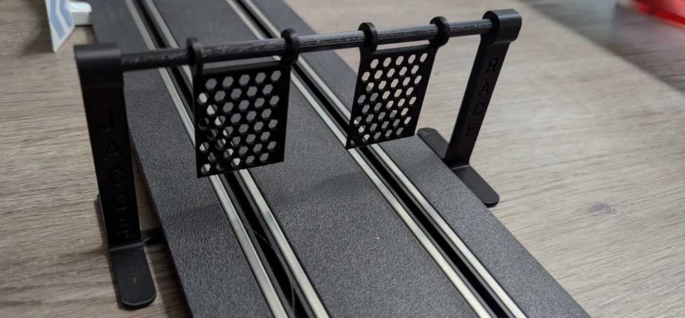
My son received a Carrera race track for his birthday. He loves it! I recently started learning CAD and 3D printing and quickly built a simple dual-flap system that flips when the car crosses the finish line. It was simple, cost less than 1$ to print.
However, looking at the design, I could see some potential improvements.
- The flap was flipping well, but there was some friction since the rod and the flaps were all made of plastic
- I enjoy racing around, but it would be interesting to get the best time
- It was a little shaky: the flaps were moving on the rod and the whole structure was moving as the car was crossing (after several crossings)
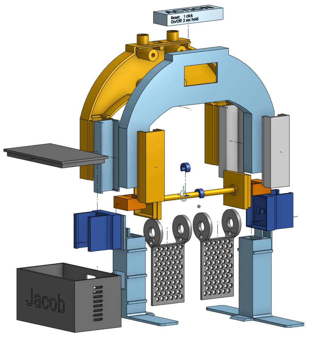
The first point made me think of bearing, and after some research, my hypothesis proved to be correct. I ordered some and added them, which changed the initial design. The flap got bigger.
The third point is that I added a small notch that goes under the track, as well as an arc between the two columns. It solidifies the structure and avoids some of the shakiness.
The second point opened a whole can of worms.
Task
The main task in tackling the challenge of counting the best time of a lap was to incorporate some electronic components. But before choosing the electronics and devices, I needed to find how I could detect a lap. My son and I like the effect of the car "crashing" into the rotating lap. So, I started with this idea of having a counter on a rotation. Similarly to web development, adding a debouncer when adding a button would help in case the flap rotates several times. The rotation needs to activate a switch. I thought about having a piece of metal touch two other pieces to create contact, but that sounded somewhat unreliable. After searching online, I learned about "reed switch". A magnet activates these. So, I added two magnets (one per flap), and once it crosses the reed switch at the top, it activates the stopwatch.
The second challenge was to display the time. I opted for a cheap LCD screen of 1.3 inches. The LCD has a fast refresh rate and using the SH110X library makes it easy to display information using X,Y coordinates.
Printing and Trying Out
The CAD of the design was my second attempt at building a 3D project, and I had learn to make it easy to reprint without having to print everything again. Thus, I broke the race lap tracker into many parts that can clip.
The idea sounds good for saving time and materials. However, the problem was the way I broke the piece. First, it is not snappy everywhere. Some connectors (pieces of plastic that go out) were connecting into a female version that was a whole of the same size but with a surround of 0.2mm bigger. That was too much. The lack of experience caused these pieces to move more than expected. Another learning experience was that friction alone is not enough, especially with many pieces. Having a more complex plastic mechanism to snap would be better. This led to the number of pieces: too many. Not only is adding custom clipping time-consuming, but it is also not great when something needs to change. Similarly, the number of pieces complicates assembly and makes it easier for children to break the device.
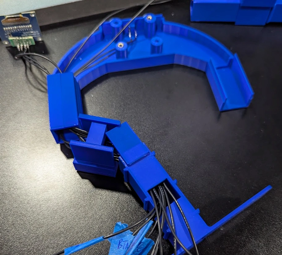
I thought of adding screws, but with so many pieces, it would also not be visually appealing. Lastly, the issue was with the wires. There are four wires from the LCD, two pairs of wires for the reed switch, and two wires from the reset button. Then, two wires for the speakers. Passing the wires through the hole is not a good design. Replacing a piece becomes very hard since the wires pass through, requiring the removal of the connection from the ESP up to the device! The design should allow us to snap/unscrew the larger piece, and once done, enable moving the wire without having to pass it through the hole. The arc part, the top one, demonstrates what the whole design should be: a front and back part that snap together. The columns are the opposite.
Electronics
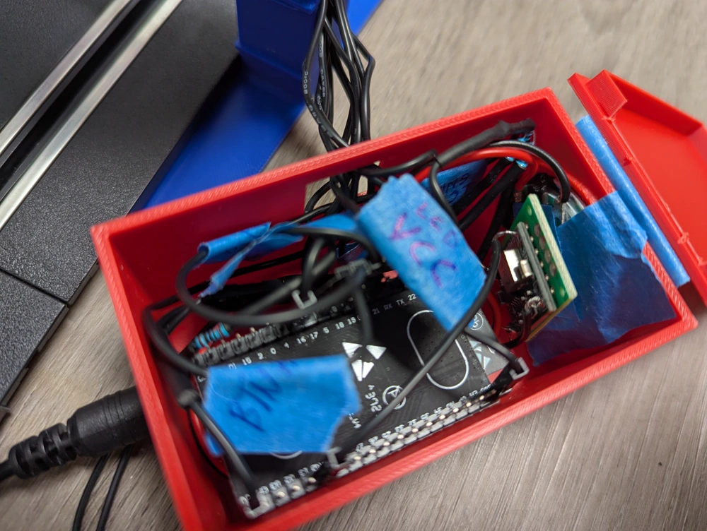
The electronic parts worked well on the breadboard, and surprisingly, I had no issue soldering and having everything into the 3D printed device. However, each wires need to connect to the ESP32. I have only a developer board, and because I might have to replace a wire, I wasn't sold on solving each wire on the board. Also, it is pretty tight, which could have led to pins touching each other. I decided to crimp the Dupont connector to every wire, and it proved to be a good solution. I also marked all wires with a tape to know where they connect to, which helped the process.
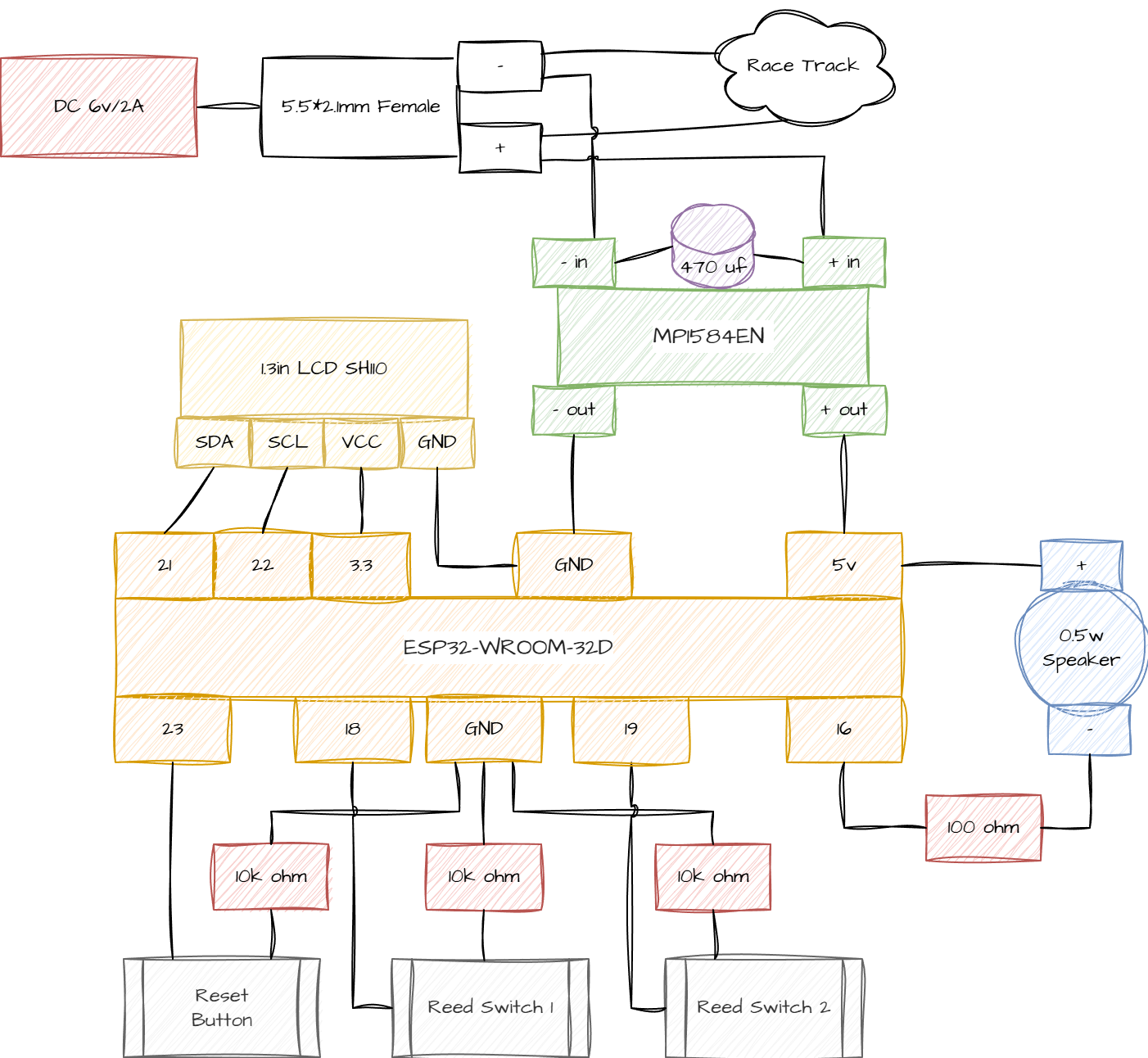
Here is the full schematic:
What is Next?
Creating the CAD even in the assembly view that allows moving pieces never shows the end result completely. I am using OnShape, a parametric CAD software, and I changed a few dimensions which adapted the whole design. Reprinting a few pieces led to incompatibility with prior pieces. The aftermath was some misalignment. While reprinting everything would work, the issue now is that the wires are all passed down, and it is a little bit annoying to re-pass all wires up. Thus, the next step would be to redesign the structure into eight pieces instead of 22, thereby avoiding many connections and holes.
Also, I noticed a few issues with the flap, the magnet, and the reed switch. The flap goes very fast since I added the bearing. I still believe the bearing is required since the plastic-on-plastic was causing a lot of friction, which sometimes was causing the flap to remain in odd positions. In software, I added debouncing and logic that does not count a lap if there are fewer than a few seconds between the last recorded time. However, another issue arises when the flap moves so quickly that the magnet does not have time to activate the reed switch. I am designing as I write a small modification to the flag that will bring the magnet closer to the reed switch.
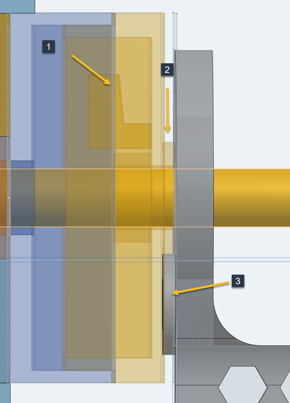
In the image, you can see the arrow #1 pointing to the reed switch holder, #2 a 1mm spacer that is next to the bearing, allowing a smooth rotation and not plastic-to-plastic friction, and #3 the new addition of 1mm closer to the reed where the magnet will sit. The flap rotation moves the magnet up, and the minimum distance goes down to 2 mm instead of 3mm. Also, now, I have space to add two magnets on each flap, which could increase the magnetic field. We will soon see if it solves the issue!
To recap, the wins are that the printed device is a lot of fun, even if not perfect for now. The design is solid, and it does not shake when cars hit the flap. Having mechanical parts that move are great, the audio makes it more alive, and the LCD showing rapidly moving numbers makes it more dynamic. The negative aspects that need to be addressed are the ease of maintenance and ensuring the reliability of the time recording when a car hits the flap.
Here is a video with the altered flag, which is smaller, addressing issues where the car would get stuck when the flap was going down and the car was crossing (the flag was positioned at 45 degrees toward the car, blocking the car's movement). The video has the sound of the system (as well as my kids talking).
Edit (August 19th)
The reed was set in place with hot glue. For some reason, one side started malfunctioning. Upon rotating the flap, the magnet did not activate the reed every time (skipping over 90% of the time). I hypothesize that I damaged the reed during the permanent installation. To fix the issue, I removed the glue and the reed switch, then reinstalled it with less glue and more slack in the wires. It has been working well so far.
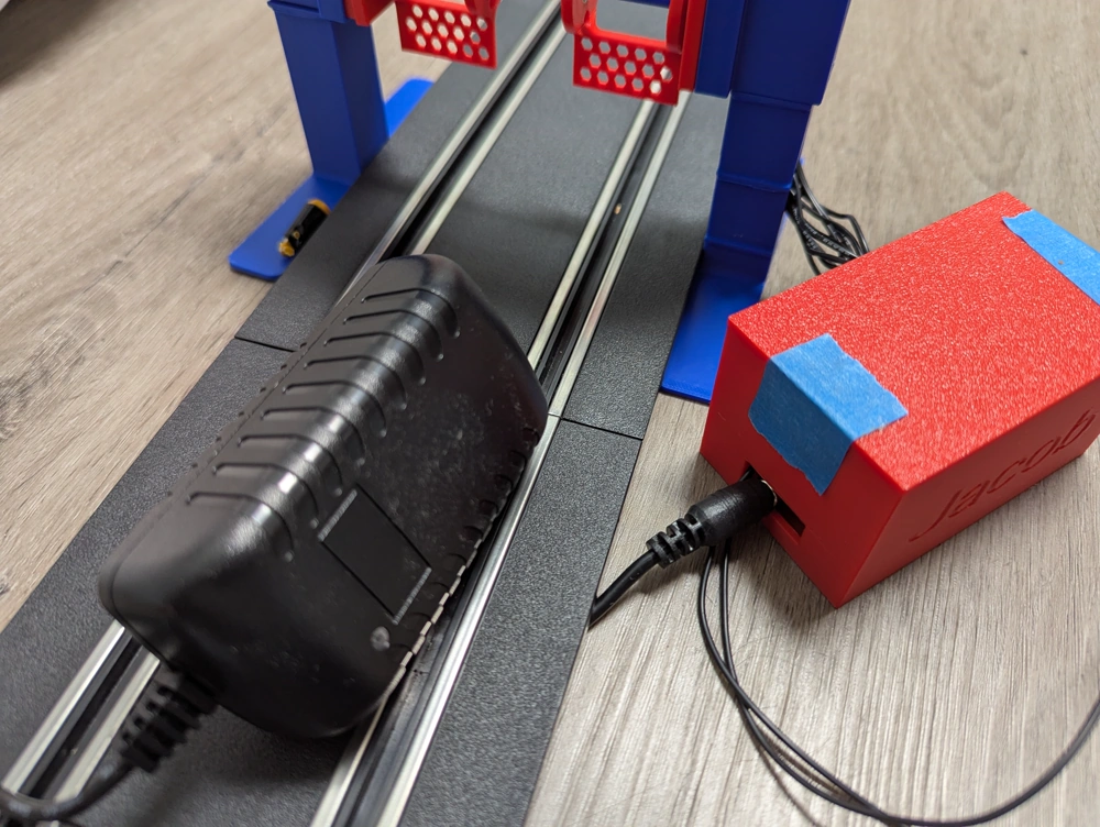
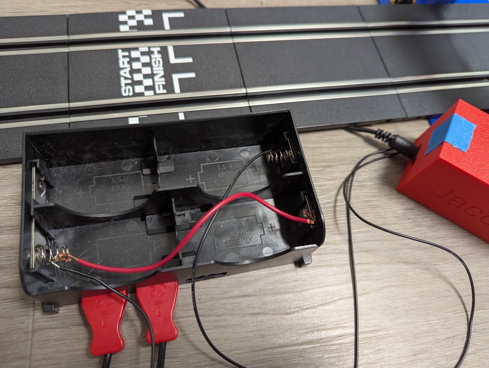
I added a female connector in the box of the ESP. It gets the power from a wall adapter that has a male part. The female redirects the 6V/2A into the track, but also into a buck converter to get 4.9V to power the ESP32. That is great because the Carrera power supply is 35$ and the lap counter is 99$. The total of $134 is a lot higher than the cost of the wall adapter ($5), the buck converter ($4), the ESP ($5), the LCD ($5), a few materials, and PLA ($10). So, for about $30, I have a lot more and customized it exactly the way I want. But the most important thing: I learned CAD design, using LCD and ESP to create something that my son is very impressed with, as it came from a roll of plastic.
Carrera's electric plug has a proprietary input. However, using the secondary power supply, the battery, is not an issue. I will solder the solution soon.
I am glad I had kept a more "freestyle" form inside the box with additional space allowing the buck converter to sit next to the ESP32.
Here is the cheap DC wall plug that has a 5.5*2.1mm male part that connects into a 2.1mm female part.